

4.1.3 Striping
In dealing with high performance networking applications, end-to-end bandwidth demands often cannot be met by the individual port rates of currently available wide-area transmission equipment. In particular, the Aurora, Casa and Nectar testbed SONET equipment available at the beginning of the testbed program had only 155 Mbps physical and/or logical channels for host connections, with aggregation of the channels required to fully use the total available bandwidth. In addition to addressing the immediate problem, this aggregation, or striping, work afforded an opportunity to investigate the wide-area rate mismatch problem more generally.
A number of choices are available for implementing a striping solution [2]. These include the amount of data to be sent in each striped increment, the protocol layer in which the striping is performed, and the topological point at which it is applied. Choices for the striping unit include byte, word, cell and packet; layer choices include physical, link, network, transport and application; topological points include physical link connections, subnet interfaces, and user endpoints. Some choices constrain others-for example choosing a physical link within an ATM network as the topological point clearly constrains the layer and striping unit choices. Because of skew introduced by different delays in each striped channel due to multiplexing equipment and switches, key factors which must be dealt with are synchronization, buffering, and reordering processing.
ATM Striping
The Aurora testbed had OC-12 SONET interfaces available at each site. These interfaces required the customer interfacing equipment to multiplex/demultiplex four 155 Mbps STS-3c SONET channels to/from a single 622 Mbps STS-12 SONET channel.
For the ATM portion of Aurora, striping was implemented at the topological endpoints by Bellcore as part of their workstation host interfaces developed for the testbed, with the 53-byte ATM cell chosen as the striping unit (Figure 4-5).
Figure 4-5. Aurora Bellcore ATM/SONET Striping
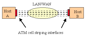
Since one or more ATM switches were in general part of the network path between hosts, the striping mechanism had to deal with skew introduced by both SONET equipment and switch queuing. A separate VC was used for each of the four 155 Mbps ATM channels and AAL5 used to frame the host PDU. The cells of the AAL5 frame were then striped across the four VCs in round-robin order, with the AAL5 end-of-frame bit set in the ATM header of the last cell sent in each of the four channels (rather than just in the last AAL5 frame cell, as would normally be done). To simplify synchronization at the receiver, the first cell of a new PDU is always sent in one of the four channels which has been designated the "first" one. The receiving host reorders the arriving cells into a standard AAL5 PDU.
A distinctly different approach to striping was used in the Nectar testbed. One of the goals of Nectar was to explore generic methods for interfacing local high-speed networks to a general wide-area ATM/SONET network with lower-speed channels, and so the local-to-wide area interconnection point was chosen as the topological striping point (Figure 4-6). This testbed used 800 Mbps HIPPI for local distribution at each site, with the sites connected by a 2.5 Gbps SONET link. The link was terminated at each site by experimental ATM/SONET multiplexing equipment developed for the testbed by Bellcore and CMU, with the 2.5 Gbps channel divided into 16 STS-3c 155 Mbps SONET channels for ATM interfacing within the equipment.
Figure 4-6. Nectar ATM/SONET Striping
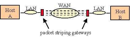
Consideration of equipment design complexity and cost associated with the choice of byte, cell, and packet striping units led to the selection of a packet striping unit, where packets in the initial implementation consisted of HIPPI frames. A distinct ATM VC is used for each 155 Mbps stripe, with the HIPPI frames which are received on the set of VCs sequentially combined into the original HIPPI stream for delivery to the local destination. This simplification is at the expense of performance, however, since at least four packets must be available for striping to achieve the full 622 Mbps rate when four 155 Mbps channels are used-if only one packet is sent, it will be at a rate of 155 Mbps.
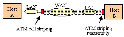
More general approaches to striping over ATM networks were explored by MIT as part of the Aurora testbed work, and in particular for cases where striping is introduced at points internal to the end-to-end path between hosts. This work examined different methods for achieving ATM layer striping synchronization in great detail, along with the tradeoffs associated with higher-layer striping choices. The conclusion was that ATM layer striping, introduced, say, at a point of local-to-wide area connection, coupled with destination host cell reordering will provide the broadest support for different choices of higher layer protocols and topologies (Figure 4-7).
Figure 4-7. Integrated ATM Layer Striping
In two of the testbeds, Aurora and Casa, variable-length packets were striped directly across wide area SONET transmission channels at the local-to-wide area connection points within the testbeds.
For the PTM portion of Aurora, IBM designed and implemented a stand-alone device called the SIA (SONET Interface Adapter), which has an optical fiber connection on one side to the OC-12 interface of wide area SONET carrier equipment and an optical fiber connection on the other side to a Planet switch. In this case the striping traverses SONET equipment on the links between each Aurora site, but does not include switches within the striped paths. The PTM operation of the network made either packets or bytes the natural choice for the striping unit, with byte striping chosen for implementation. SONET-level framing information for each STS-3c payload envelope is used by the receiving SIA to determine skew and control byte reordering of the FIFO buffer outputs from each STS-3c channel. To reduce complexity of the SIA design, transmission of each new packet is always begun using the first STS-3c payload envelope of an STS-12 frame.
In the Casa testbed, SONET termination equipment at each site provided eight distinct OC-3c physical interfaces on the user side, which were multiplexed by the SONET equipment directly into a 2.5 Gbps OC-48 intersite trunk. Thus an aggregate bandwidth of 1.2 Gbps was available for use between each pair of sites which were directly interconnected. A HIPPI-SONET gateway device was developed by LANL to interface each site to the SONET termination equipment, with striping used to send 800 Mbps HIPPI streams across the aggregated 155 Mbps channels (Figure 4-8). The remainder of the 1.2 Gbps trunk channel was used for error correction data and for spare capacity in the event of individual channel failures.
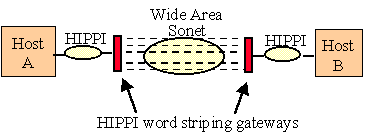
As in the Aurora PTM case, Casa striping was applied at the endpoint of each intersite link, with each link assumed to contain wide-area SONET equipment but not switches and with variable-length packets mapped directly into SONET frames. Since all Casa sites used HIPPI for local switching and host interfacing, and the gateway was designed to provide efficient HIPPI-SONET communications, the unit of striping was chosen to carry two 32-bit HIPPI words plus four per-word overhead bits, for a total striping unit of 72 bits. The actual trunk bandwidth used could be matched to a site's needs, ranging from a single 155 Mbps channel to the use of six channels to carry the full 800 Mbps HIPPI rate along with an FEC channel and a spare channel. A combination of SONET framing detection and payload control information is used by a receiving gateway to perform skew compensation and reassemble the source data stream.
Overall, the testbed implementations revealed that skew can be introduced from a number of different sources, and that considerable care must be taken to ensure that correct destriping is achieved for all cases if full striping performance is to be achieved. The general ATM-layer synchronization methods explored MIT provide a way to avoid dependence on lower and upper layer functionality while also achieving topological flexibility, and may provide a good basis for standardization in the ATM networking case. The two PTM striping cases both make use of SONET framing information to accomplish striping synchronization, but differ in the details as well as in their choice of striping unit. Further work is needed to determine what direction should be taken for standardization in the PTM case and to deal with hybrid ATM/PTM situations.